Clutch and brake selection varies depending on the industry and specific application requirements. As such, there are a variety of clutch and brake options available based on the requirements of the machinery with which they will be used. In any use case, however, determining torque requirements is essential for selecting the appropriate clutch or brake. This blog post will help readers understand the methods for determining torque to facilitate accurate sizing of clutch and brake solutions.
How To Calculate Static Torque

Some applications require that acceleration or deceleration occur within a specific amount of time. Determining the appropriate clutch or brake size for these situations begins with determining the dynamic torque required to stop or start the load. Consider the following variables:
- I – Rotational load inertia, lb-in-sec2
- ω – Differential slip speed, rpm
- t – Time to speed, sec
- D – Load drag torque reflected to the clutch (lbs./in)
- Note: 0.1047 is a factor that converts rad/sec to rpm
Using these variables, here is the equation for determining dynamic torque:
- TD = 0.1047(Iω)/t – D
Multiplying the equation’s solution by 1.25 will convert dynamic torque to static torque.
To demonstrate this equation in action, here is an example used to determine the appropriate size Power Off Spring Engaged Brake for a paper feed roller. We begin with our equation:
- TD = 0.1047(Iω)/t – D
- I – Total system rotational load inertia at the reflected at the brake shaft, 0.04 lb-in.-sec2
- ω – Differential speed, rpm -1200
- t – Time to stop, 0.040 sec
- D – Load drag torque reflected to the brake =10 in. lbs.
Here’s what the equation looks like with these values filled in:
- TD = (0.1047(0.04*1200)/0.040) – 10
- TD = (0.1047(48)/0.040) -10
- TD = (5.0256/0.040) -10
- TD = 125.64 -10
- TD = 115.64 in. lbs.
Now convert our dynamic torque findings to static torque by multiplying by 1.25.
- TS = TD*1.25
- TS = 115.64 (1.25)
- TS = 144.55 in. lbs.
- TS = 144.55/12 = 12.04 ft. lbs.
As a final result, the paper feed roller would require a Power Off Brake capable of at least 12.04 ft. lbs. static torque. As such, we would select a SEPAC SEB-340-2 Spring Engaged Power Off Brake with a 14.5 ft. lb. rating.
How To Calculate Holding Torque

For use cases that have a motor, drive, and a gearbox, it’s important that the brake be located at the high-speed end—most commonly the motor end. Mounting the brake on the motor end allows a smaller brake to be used, but it’s still important to properly calculate the torque required to hold the load. Determining this torque requires working backwards from the load using this formula:
- TH = (T/GR) * K
Here are the relevant variables:
- TH – Required holding torque
- GR – Gear ratio
- K – Service factor
As an example, the output torque from the gearbox is 500 in. lbs., which is what’s required to drive the load. We will use a service factor of 1.5, though service factors may vary from 1.5 to 3.0 depending on the operating environment and various other application-specific data. This means that the holding torque would be determined as follows:
- T/GR * 1.5
- Gear Ratio = 10 to 1
- 500/10 = 50 * 1.5 = 75 in. lbs.
- Dividing by 12 gives us 6.25 ft. lbs.
For a requirement of 6.25 ft. lbs., we would select a SEPAC SEB-340-1 Spring Engaged Brake rated to 8.0 ft. lbs.
Calculating Holding Torque for a Clutch Application
When information about torque is unavailable, the horsepower of the motor can be used with a general formula to get a ballpark figure for Clutch requirements. Here is the formula:
- T = 1.25 x 63,024 x ((P x K)/ω)
Here are the variable definitions:
- K= safety or service factor (life/wear)
- P = motor output power, hp
- ω = motor speed, rpm
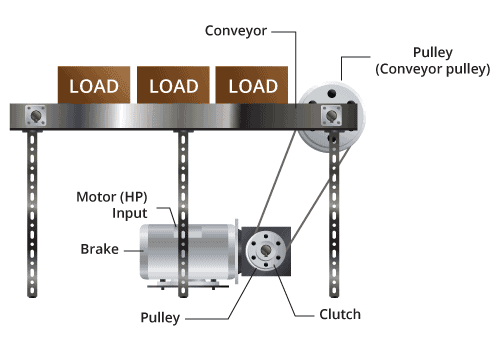
A 7 HP DC motor runs at 1800 RPM and drives a conveyor through a 15 to 1 gearbox. The operator would like to disengage the conveyor from the motor to clear a jam without stopping the motor or the gearbox output, simply by turning a clutch on and off. Note: The clutch is located after the gearbox and the shaft speed after the gearbox is 1800/15 or 120 RPM.
To determine the clutch torque rating needed, calculate:
- T = 1.25 x 63,024 x ((P x K)/ω)
- T= 1.25 x 63,024 x ((7 x 1.5)/120)
- T= 1.25 x 63,024 x ((10.5)/120)
- T= 1.25 x 63,024 x (0.0875)
- T= 6893LB-IN. Or 574 FT-LB.
SEPAC SFTC-630 Electromagnetic Stationary Field Tooth Clutch is a solution. It is rated at 650 LB-FT
Calculating Holding Torque for a Brake Application Mounted on an Arm

In certain applications, mounting a brake on an arm will hold a load from falling in the event that power fails or is removed. For these instances, determining load torque requires the holding torque and the weight of the arm (force x distance) multiplied by a service factor of 1.5. Here is the formula:
- TH = WL + WA x R x 1.5
- TH= Weight of the arm (lbs.) at R + load (lbs.) * distance (R) * 1.5
Here is an example with some variables plugged in:
- R = 12”
- WA= Weight of arm at R = 2 lbs.
- WL = Weight of load = 10 lbs.
- TH = 10+2 * 12” = 12 * 12 = 144 in. lbs. * 1.5 = 216 in. lbs.
- 216 in. lbs. divided by 12 = 18 ft. lbs.
Using a General Formula When the Load or Holding Torque is Unknown
When information about holding torque or load torque is unavailable, the horsepower of the motor can be used with a general formula to get a ballpark figure for brake requirements. Here is the formula:
- TH = 1.25 x 63,024 x ((P x K)/ω)
Here are the variable definitions:
- 25 = a factor added to account for holding the load, in addition to stopping
- P = motor output power, HP
- ω = motor speed, rpm
- k= service factor
As an example, here is the torque required to stop a 2 horsepower motor that rotates at 1800 rpm:
- 25 * 63,024 * (2 * 1.5)/1800)
- 25 * 63,024 * 0.00166 = 131.3 in. lbs.
- 3 in. lbs./12 = 10.94 ft. lbs.
As such, a SEPAC SEB 340-2 Spring engaged Brake rated at 14.5 ft. lbs. would be most appropriate.
Clutch and Electromagnetic Brake Solutions From SEPAC
SEPAC, Inc. is a manufacturer of electromagnetic brakes and clutches, as well as other motion control products. Our custom engineering capabilities enable us to develop reliable and innovative solutions to the challenges faced by original equipment manufacturers (OEMs). We’ve provided clutch and brake solutions to demanding industries such as aerospace, robotics, military and defense, healthcare, energy, and many others. Our ISO 9001 and AS9100 certifications demonstrate our ongoing commitment to manufacturing only the highest quality products.
For help calculating the torque for your application, please visit our Torque Calculator page. This page has been developed to help our customers determine the best possible clutch or brake fit for specific applications.